Primary Applications of Rigid Flex Boards
Applications of Rigid Flex Boards
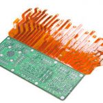
The primary applications of rigid flex board are foldable or bending electronics, wearable devices such as fitness and health trackers, and medical equipment. These devices can bend and flex while still maintaining proper connectivity, increasing durability and improving performance. Rigid-flex circuits also help with product miniaturization.
For example, a rigid flex board can incorporate multiple layers of components into a smaller package size than a traditional rigid board. This allows for greater device population in a smaller space, saving room and weight in the final product. Rigid-flex circuits are also ideal for a variety of industrial and manufacturing applications such as machine control, data collection, and robotics.
Flexible printed circuits can be more durable than rigid ones due to their layered construction and flexibility. They also allow for a smooth transition between traces, avoiding stress points where connections can break. To avoid these weak spots, designers should always transition from thin to thick traces gradually instead of abruptly. They can also use fillets to connect traces, or plated through-holes, to help with thermal stability and reduce stress at connection points.
Primary Applications of Rigid Flex Boards
Another important benefit of rigid-flex boards is the ability to streamline the design process by eliminating extra connectors and cables. This can save time, money and improve reliability by reducing the likelihood of errors during assembly. Rigid-flex circuits can also be installed in only one way, preventing user error.
Rigid-flex circuits are particularly useful for high-reliability applications where vibration and shock can damage connectors and cable assemblies. They are also well suited for rugged environments that can withstand extreme temperatures, radiation, and other environmental factors.
To achieve high reliability, rigid flex circuits should be made of high-quality materials. They should also be designed with the utmost care to prevent signal interference and other issues. To minimize the risk of failure, designers should consider factors such as layer transition, heat dissipation, and panel utilization. They should also make sure to work closely with their fabricators to ensure the design and fabrication processes are coordinating well.
A rigid-flex circuit can be designed to either be static (never bending or folding) or dynamic (flexing over the life of the product). Static applications tend to be more straightforward as they don’t require any special tools. However, dynamic applications can be more complicated as they will need to be tested for stress and torsional loads.
The first step to designing a rigid-flex circuit is to determine the desired flexing and bending radius. Once this is known, the PCB designer can begin creating a schematic and layout. The PCB can be cut and v-scored to create breakaway tabs that will allow it to be easily assembled into the finished product. The design tool should also allow the user to indicate a “bend area,” which will help the fabricator determine where to place the flex areas during the manufacturing process.
The flex areas of the circuit will then be connected to the rigid sections through a series of vias. These connections can be made with plated through-holes, or with teardrops, which are small pads used for making solder joints on rigid-flex boards. Teardrops are typically made of a polyimide dielectric with an adhesive on one side, and are ideal for connecting signal layers to rigid layers. It is important to remember that the conductive paths on a flex PCB must be properly terminated to ensure long-term reliability. The best way to do this is by using a plated through-hole with a gold or silver finish.